
The following images and videos depict the build process for the programmable Darwin-Mini robot:


connectors

This image depicts two types of connectors that will be used throughout the build process. The longer ones are 1 cm in length and the shorter ones are 0.6 cm in length. The longer connector will herein be referred to as Churro and the shorter one will be referred to as Bob (instead of the given SRV-1LSH and SRV-1SH to save us all the trouble of trying to remember which one is which.) The inside connectors will be named connector, plain and simple.
*Remember!
Churro = SRV-1LSH
Bob = SRV-1SH
Connector = 1LSP and 1SP
HANDS
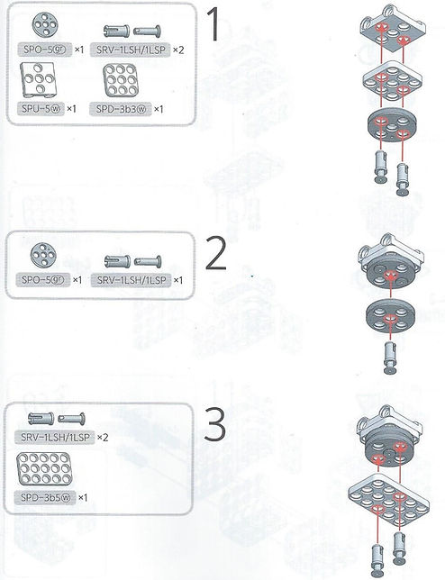


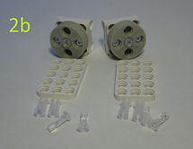

Steps 1a through 3a follow the instructions included with the Darwin-Mini. 1a shows the layout of the parts you will need to complete steps 1b through 1d. 2a shows the layout of the parts you will need to complete steps 2b and 3a. Here, we are duplicating the steps to make both the right and left hands of the robot. All of the connectors in these pictures are Churros.
HINT: Fully insert the connector inside the designated holes BEFORE inserting either the Churro or the Bob. It will make assembly easier!


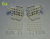


Steps 4a through 7d depict the instruction manual steps 4, 5, 6, and 7. Pay attention, though, because both hands are mirror images of each other, not the same piece built twice. Steps 4a, 5a, 6a, and 7a depict the parts you will need for the b, c, and d steps. 4a shows Bobs, 5a shows Churros, 6a shows Bobs, and 7a shows Churros.
wiring the motors

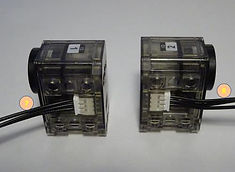
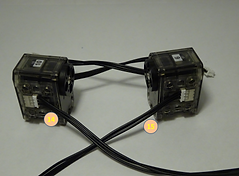
The wires shown to the left are labeled as Cable-11, Cable-13, and Cable-16 in the parts list. This means that the cables are 11cm, 13cm, and 16cm long respectively. Both ends of the wires have the same connectors and can be inserted into the motor from either side.
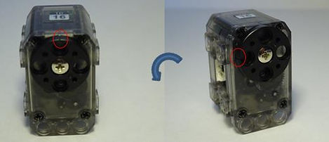
When wiring the motor, the orientation of the connector is very important. The picture on the bottom left shows the connector with the correct orientation before it is inserted into the motor. The picture on the bottom right shows the wire fully inserted into the motor.


arms

You will need motors ID 3 and 4, 8 Bobs, 2Cable-11 cables, and 2 DMF-B04 pieces.


Connect the Cable-11 cables to the corresponding sides of the motors as shown in the picture. The cables are labeled with numbers to connect them to their correct places on the OpenCM9.04-C board.


Insert the wires from motors 3 and 4 into the openings shown in the pictures to the left. Next, orient them so that the sides of the motors are flush with the inside of the DMF-B04 pieces. Use 4 Bobs on each of the motors to secure the pieces together.

Here, you will need motors ID 5 and 6. Motor 3 corresponds to motor 5 and motor 4 corresponds to motor 6. You will also need 2 Churros, 2 grey wheels, and 8 M2X4 Phillips screws with the screwdriver from the kit.


Orient the motors and the grey wheels as shown in the picture to the left. Notice that the black control wheels of motors 3 and 5 face the same way as do the black control wheels of motors 4 and 6. Place the grey wheels opposite the black control wheels and insert a Churro in the middle of the wheel to keep the pieces together. On the opposite side, screw the motor wheel in place. Finally, direct the cables into the sides of 5 and 6 shown in the picture to the right.


Finally, use 4 Bobs to connect each hand to the bottom of motors 5 and 6. Use the flanges on the “wrists” of the hands and the flanges on the bottoms of the motors.
feet


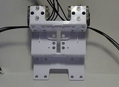
To start the feet, you will need 2 Cable-11 cables, 8 Bobs, motors ID 13 and 14, and 2 long rectangular pieces. Insert the cables into the sides of the motors shown in the middle picture. Fix the long plates onto the sides of the motors with the cables attached with 4 Bobs each.


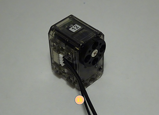
You will now need motors ID 15 and 16, 8 M2X4 Phillips screws, and 2 small rectangular plates with holes for the screws. You will also need the STL tool in order to change the start position of the motors. Turn the motor control wheel of motor 15 and 16 to the positions shown:

[Motor 15]
[Motor 16]

Attach the rectangular plates to the control wheels of motors 15 and 16 using the screws.


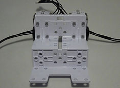
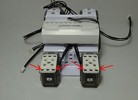
Gather 8 Bobs and motors 13, 14, 15, and 16. Motor 13 corresponds with motor 15 and motor 14 corresponds with motor 16. Attach the cables to the corresponding motors as shown in the middle picture. Using 2 Bobs on each motor, connect the rectangular pieces together as depicted by the red arrows in the picture to the right. In order to attach the 4 remaining Bobs, you will have to turn motors 15 and 16 90 degrees. The following video captures the movement:


In order to attach the motors to the feet, you need 8 Bobs. The picture to the right shows the front view of the feet. The following video shows a 180 degree rotation of the feet from front view to back view, displaying the location of the Bobs as well:


Insert 4 Bobs into the bottom of each foot and secure the grey, flat plates to the bottom of each foot with 4 M2x4 screws.


The final step of the foot process is to connect the beginning part of the legs. You will need two grey wheels, 8 M2x4 screws, 2 DMF-B05 pieces, and 2 Churros. Connect the grey wheels on the opposite sides of the black motor control wheels and attach them to the DMF-B05 pieces using a Churro. Connect the black motor control wheel to the DMF-B05 pieces using the screws.
BODY FRAME

Gather motors ID 1 and 2, 2 square pieces with flanges, 4 Bobs, and 4 Cable-13 cables.


Attach cables onto motors 1 and 2 as shown in the far left. Wrap the cables under the motors and attach the square pieces with 2 Bobs on the back sides of each motor only.


You will now need to attach motors 1 and 2 to the DMB-B02 (body frame). Position the motors as shown in the second picture and attach them with 2 Bobs each as shown in the third picture. Finally, use 8 Bobs to secure the sides of the motors to the body frame.


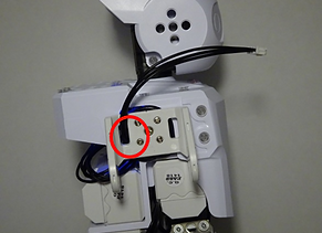
Gather the LBB-040 (battery holder) and 4 Bobs. Place the battery holder onto the body frame, being careful to orient the cable towards the side of motor 2. Attach the battery holder to the body frame as shown in the third picture with 4 Bobs and loop the cable into the opening as shown in picture 3. Take 2 more Bobs and insert them into the body frame where the red arrow points in the picture to the far right.


Take 2 square pieces with flanges and 8 Bobs and attach them to the body frame as shown above.

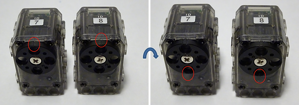
The next phase involves motors ID 7 and 8, 4 Bobs, and 2 Cable-16 cables. Use the STL tool to turn the motor control wheels on motors 7 and 8 180 degrees. The single mark should now be downward and the double mark should be upward.


Insert the cables into the sides of the motors as shown above. Use the 4 Bobs to attach motors 7 and 8 onto the body frame and guide the cables into the opening as shown.


This time, the second battery holder will be attached to the frame on the side of motors 7 and 8. Use 4 Bobs to connect the battery holder to the frame as shown in the middle picture and guide the cable through the opening. Finally, use two more Bobs to finish attaching the battery holder to the frame as shown in the picture to the right.


It is now time to insert the lithium-ion battery cases into their holders. Make sure the grooves on the sides of the battery cases match the battery holders.


Take 2 rectangular plates with mounting holes, 8 M2x4 screws and mount them onto the motor wheels of motors 7 and 8.


Motors 9 and 10 will have two different cable sizes attached to them. The first two are Cable-11 cables. Attach them as shown in the second picture. These cables will be labeled as 13 and 16. Next, attach two Cable-13 cables in the opposite ports as shown in the picture to the far right. These cables will be labeled as 14 and 15.


Take the rectangular plates shown above and attach them to the motors using 2 Bobs on each plate as seen in the middle picture. Place the square pieces with flanges beneath the motors, making sure to loop cables 14 and 15 underneath the motors before attaching the square pieces. The bobs connect to the flanges of the square pieces.


Use 4 Churros, 2 on each motor, to mount motors 9 and 10 to 7 and 8 respectively. The picture in the middle shows the arrows pointing to the location of the Churros before mounting. The picture on the right shows the mounted motors.


Take cable 15 from motor 9 and attach it to the side of motor 7 as shown in the picture to the left. Take cable 14 from motor 10and attach it to the side of motor 8 as shown in the picture to the right. Motors 9 and 10 will be turned 180 degrees in order to attach 4 more Bobs and secure the motors. The following video shows the movement:

The image above shows the location of Churros and Bobs remaining on the frame.
BODY plate


Take the dummy motor from the kit and attach it to the body plate as shown in the middle picture. Use 4 M2x6 screws to fix the dummy motor to the body plate.


Attach the OpenCM9.04-C and the BT-210 to the underside of the body plate as shown in picture 3. A total of 8 Bobs will be needed for the attachment, using 4 on each component. The Bobs used on the OpenCM9.04-C are attached into the OpenCM9.04-C first and will then clip into the body plate. The Bobs used on the BT-210 attach from the body plate first and clip onto the BT-210, as shown in the picture to the far right.
****************************************************IMPORTANT STEPS*****************************************************


Use the diagrams above to locate the cables into the correct spots on the OpenCM9.04-C board. Your wires should look like the following picture once fully installed:


Place the body plate onto the body frame and attach 4 Bobs on the left side of the robot and 4 Bobs on the right side.
head


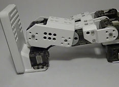
Attach the head to the body frame’s dummy robot using 4 Bobs as indicated in pictures 2 through 4.
legs

The robot’s left leg will be built next. Take motor ID 12 and attach a Cable-11 cable as shown in the picture to the right.


Take the unattached cable from motor 10 and guide it through the opening of the DMF-B04 piece as shown on the left. Slide the grey wheel between the DMF-B04 piece and motor 10. Take the wire from motor 10 and insert it in motor 12.


Fix the DMF-B04 piece to motor 10 using 4 M2x4 screws and a Churro on the grey wheel. Attach motor 12 to the DMF-B04 piece by using 2 Bobs on the left side, 2 Bobs on the right side, and 2 Bobs on the front side.
*The following images depict the build process of the robot’s right leg. Since they are mirror images of the procedures for the robot’s left leg, only the images will be depicted without comments.


attaching the legs and feet


The foot in the first picture belongs to the robot’s left leg. Take the unattached cable from motor 12 (cable 18) and attach it to motor 14 on the foot, being careful to keep the cable BEHIND the DMF-B05 piece. Use a grey wheel between the motor and the DMF-B05 piece (as shown in picture 2). Attach the lower leg to the upper leg by inserting a Churro where the grey wheel is located and screwing 4 M2x4 screws onto the motor control wheel as shown in pictures 3 and 4 respectively.


These pictures depict the assembly of the robot’s right leg. They are mirror images of the procedures for the left leg.
attaching THE ARMS AND BODY
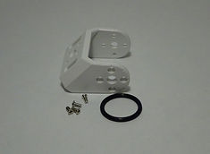


Before attaching the robot’s arms, a link must be placed on both the left and right “shoulder sockets.” For the left arm, take the O-ring (STR-20) and loop the cable inside, as shown in picture 2. Loop the O-ring around the motor control wheel and place the DMF-B03 piece over it, securing it with 4 M2x4 screws. Make sure to loop the cable through the right side of the DMF-B03 piece, as shown in picture 4. Also make sure that the flanges point downward, not upward.


Using the same parts as for the left “shoulder socket,” assemble the right “shoulder socket.”


The arm with motor ID 4 on top is the robot’s left arm. Insert the cable from the body into the remaining port on motor 4. Use a grey wheel, a Churro, and 4 M2x4 screws as in earlier steps to connect the arm onto the “shoulder socket.” Keep the arm pointing straight down when attaching the screws. In the orientation shown in the picture to the right, the single notch on the motor control wheel should be located where the arrow is pointing.


The procedures for attaching the robot’s right arm are a mirror image of the procedures for the left arm. The picture on the right points to the motor 3’s single notch.
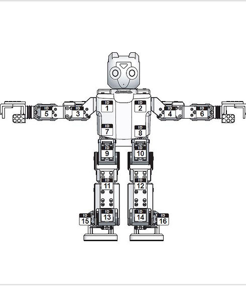
motor id map
fully assembled

A comprehensive user manual can be found at http://support.robotis.com/